Product Description
| TP5000 Lithium-Ion Battery, LiFePO4 Battery, 1A Current, 4.2/3.6V Function: Charges lithium and lithium iron phosphate batteries. Automatically stops when fully charged. Red and green dual-light indicators. Dimensions: 21.5*14.5*4.2mm Instructions: TP4056 and 4057 charging boards are used in the same manner. 1. For lithium batteries, simply connect the B+ and B- outputs to the battery. A red light will illuminate during charging, automatically stops when fully charged, and a green light will illuminate when charging is complete. 2. For 3.6V lithium iron phosphate batteries, simply open the solder joint between the two pads with a soldering iron. The power supply and battery connections remain the same as above. To switch back to charging 4.2V lithium batteries, simply use the pads to dip solder and reconnect. |
| Product Introduction: Advantages: Switching buck mode offers higher efficiency and significantly lower heat generation than linear charging circuits. Charging current is 1A, maintained at 1A throughout the constant current charging cycle. No additional heat sink is required, minimizing the impact of heat on the charging current. Charging time is shortened. Compatible with standard lithium-ion, lithium-polymer, and lithium iron phosphate batteries, with settings adjustable via a single jumper. |
| Parameters: Input: 4.5-9V Output Voltage: 4.2V/3.6V ±1% (the circuit board defaults to 4.2V for lithium-ion batteries) Output Current: Default: 1A The efficiency test will be described in detail later. If you are testing efficiency yourself, we do not recommend testing the battery voltage. Please note that you should skip the 0.1 ohm resistor test at the RS sampling point. During the test, placing the input power supply close to the circuit board and minimizing the wiring length will affect the efficiency test. We recommend increasing the input capacitance. For voltage and current testing, it is recommended to use a high-precision ammeter in series rather than reading the power supply directly from the digital display. For current testing, you can connect the battery directly in series with the positive terminal. Simply ensure that the battery voltage is below 3.9V using a high-range ammeter. |
| Features: The entire panel features precious metal ceramic capacitors with X7R temperature characteristics, offering performance, safety, and stability far exceeding tantalum capacitors! Copper tape inductors with a high current of 5A and a compact design, featuring fully enclosed magnetics for low loss and low interference! Single-sided machine mountable, ultra-thin 4mm design offers excellent heat dissipation with a compact footprint. The exposed copper backside facilitates mounting and heat sink attachment. Based on a DC-DC step-down circuit, it offers significantly higher efficiency and lower heat generation than linear charging circuits. The charging current is 1A, but the input current is only approximately 0.7A. Optional lithium iron phosphate batteries or standard lithium-ion/lithium polymer batteries are easily adjustable with a single jumper. Compact, the size of a dime, it charges at 1A without the need for additional heat sinks. Overheat protection automatically reduces the current to prevent burnout. High-precision resistors throughout the panel, featuring large 1210 precious metal multilayer ceramic capacitors with the most stable temperature characteristics. Auto-stop upon full charge, dual-color charging status indicator. |
| Finished Product Parameters: Dimensions: 21.5mm*14.5mm*4.2mm Ultra-thin and compact, about the size of a dime, single-sided mountable with reflow soldering Input: 4.5-9V (recommended not to exceed 7V) Output Voltage: 4.2V/3.6V, ±1% selectable via jumper Output Current: Default 1A, customizable 0.5-2A; heat sink required for outputs above 1.5A 4 terminal blocks, 2 for input, 2 for batteries, and soldering locations for in-line LEDs |
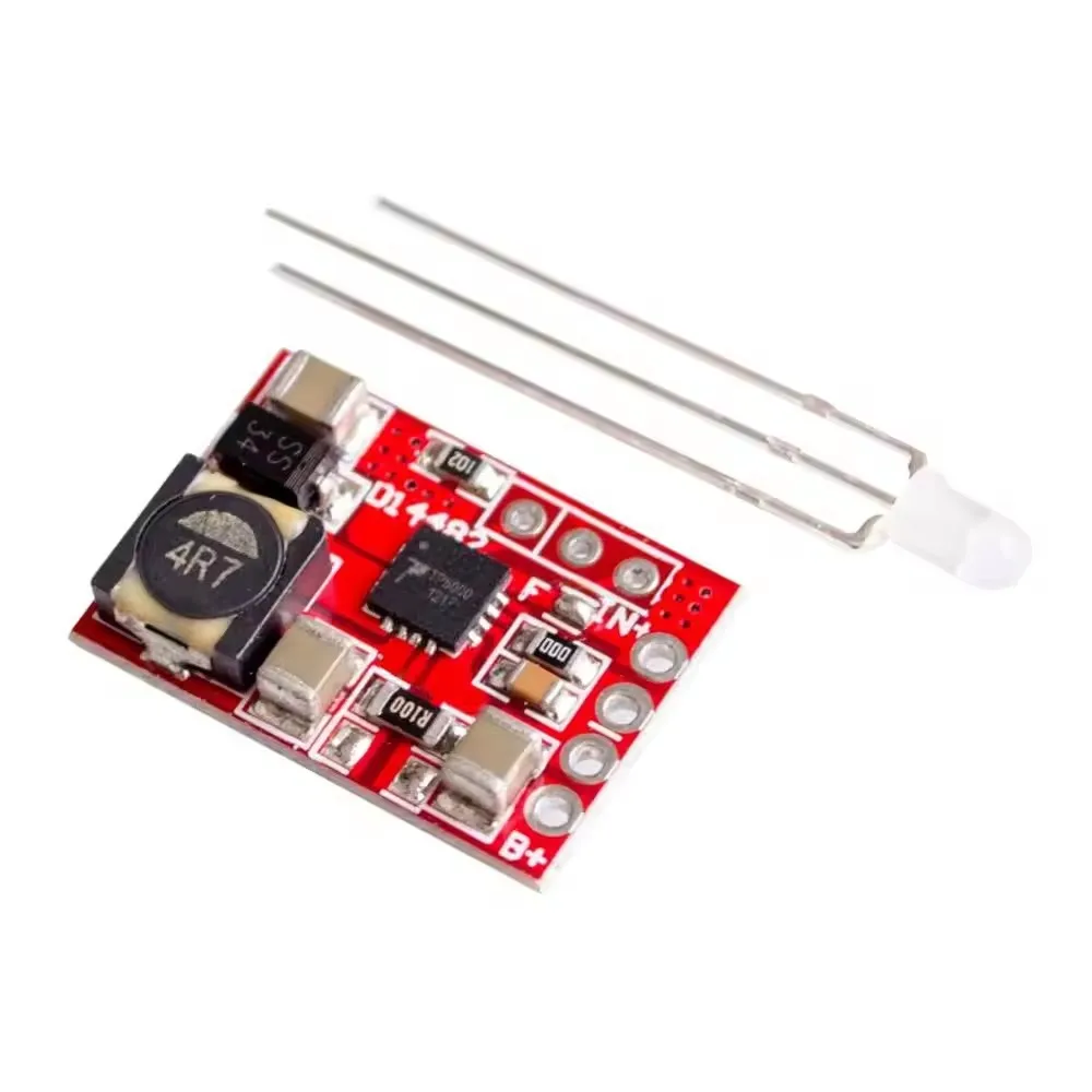
| Instructions: The circuit comes with a red-green or red-green LED. You need to solder it to the circuit yourself, as shown in the product image. Place the longest leg in the middle, the medium-long leg near the chip, and the shortest leg near the outside. Connect a 4.5-7V power supply to the power terminal. The current must be greater than the charging current; the green light will illuminate. Connect a lithium battery or lithium iron phosphate battery to the battery terminal. If the battery needs charging, the red light will illuminate. If you need to adjust the current, adjust the current sampling resistor to the desired value. The sampling voltage is 0.1V, and the current is 0.1/resistor value. A 0.1Ω resistor is already soldered to the circuit, and one slot is empty. Solder a 0.2Ω resistor to the empty slot and set the current to 1.5A. Solder a 0.1Ω resistor to the empty slot and set the current to 2A. Remove the existing R100 (0.1Ω), solder a 0.2Ω resistor, and set the current to 0.5A. For charging currents greater than 1A, it is recommended to install a heat sink. If you are charging a standard lithium battery (3.6 or 3.7V, cutoff voltage 4.2V), please place a drop of solder on the solder joint marked F on the circuit board to connect them. If you are charging a lithium iron phosphate battery (3.2V, cutoff voltage 3.6V), please remove the solder from the solder joint marked F. |
Product Photos
Company Information
.jpg)
.jpg)
.jpg)
.jpg)