Product Description
I. Purpose: Resolving Power Supply Failure Repair Problems in 15-21-inch LCD Monitors LCD monitor power supply boards are prone to damage. The most common components are the power driver chip, high-power switching transistor, and sampling resistor. Due to the wide variety of models and types of these components, repairs are often impossible due to unavailability of spare parts.In response to customer demand, we have developed this universal power supply module for LCD monitors. This module offers advantages such as simple wiring, easy installation, time savings, and a high repair success rate. Those facing these repair challenges may consider our universal power supply module. |
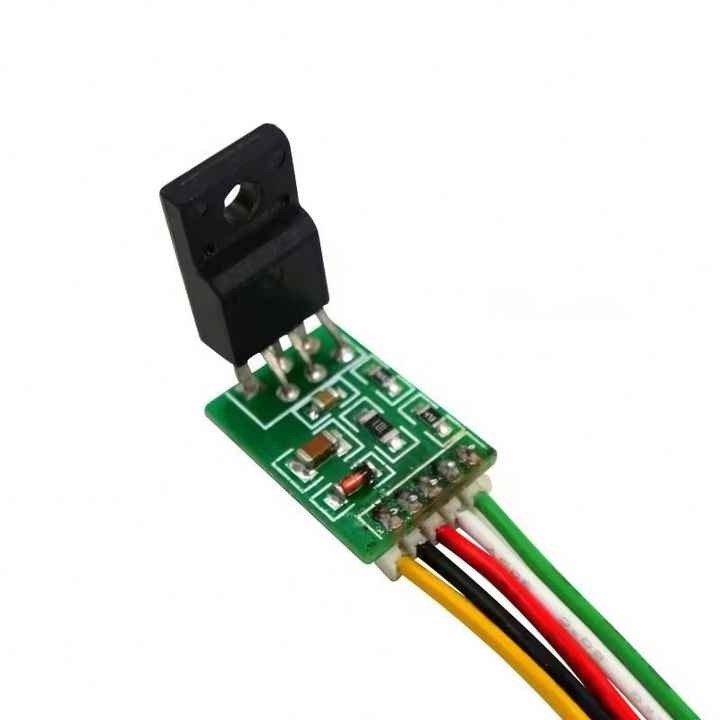
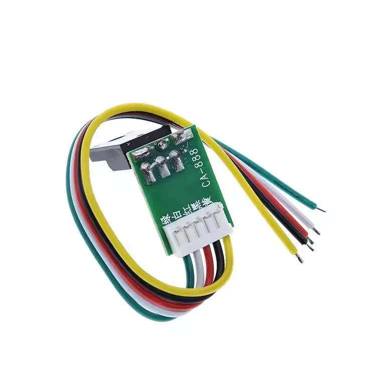
| II. Pin Definition 1. Yellow Wire: DRAIN, power control terminal. Connect to the D terminal of the original high-power MOS power transistor. This is usually the middle pin of the power switch. 2. Black or Pink Wire: GND, module ground (300V). Connect to the negative terminal of the capacitor. Both can be on the same line. Connect directly to the negative terminal of the large filter capacitor. 3. Red Wire: VCC, module power supply. Connect to the positive terminal of the rectified capacitor at the feedback winding. Provides continuous power supply with a voltage between 12-18V. 4. White Wire: FB, voltage regulator feedback. Connect to pin 4 of the optocoupler. Ensure that pin 3 of the optocoupler is connected to the hot ground. If not, short the optocoupler to the hot ground and disconnect the peripheral circuitry at pin 4. 5. Green Wire: Start pin. Connect to the positive terminal of the +300V capacitor. Customers must carefully review the specific connection instructions before performing modifications. Do not connect them blindly. If you don’t understand, please read the wiring diagram below several times! |
| Part 3: Instructions: 1. Remove the power chip (usually 8-pin) and the switching transistor (MOSFET) from the original board. 2. Check the 300V capacitor and the load-side capacitor for any bulges. Replace any if any. 3. Check the load side for short circuits, AD board, high-voltage board, etc. 4. Connect the corresponding wiring of the module and carefully check for any errors. Failure to do so may cause the module to explode. 5. Install the module in the original heat sink location, ensuring proper insulation and avoiding short circuits. 6. Power on the module and measure the voltage to see if there is any output. If not, investigate the cause. |
| IV. Precautions: 1. Before using this module, please check for shorts on the cold end. Repair any shorts immediately. If the capacitor is bulging, replace it. Disconnect any shorts in the high-voltage transformer circuit. Before installing this module, remove the power chip and MOSFET from the original module. At this point, the voltage between the center electrode of the original switching transistor and the hot ground should be approximately 300V. 2. If pin 3 of the optocoupler is not connected to hot ground, connect it to hot ground. Also, disconnect the circuit around pin 4 and connect the white wire to pin 4. |
| V. Troubleshooting 1. No output: Wiring error. Avoid misconnecting or missing a connection, as this will only burn the chip. Ensure there is no short circuit on the load side, and check for issues with the optocoupler. 2. The optocoupler is not controlling properly. Pin 1 is not connected to ground, and pin 2 is connected to the VCC circuit through a resistor. 3. Severe overheating: If the tube has been used for less than 10 minutes, in addition to ruling out excessive load, check for damage to the diode and capacitor on the hot-end transformer. Unstable voltage and jumps: The load is too light or too heavy. Continuous voltage jumps indicate a light load, while hiccups indicate a heavy load. Slight voltage jumps may occur even when no load is connected. This is mainly due to differences in transformer design. Try connecting a load or testing with a 100 ohm resistor on the 5V terminal. Regarding compatibility, we have tested various power supply boards, and with so many different models, incompatibilities are inevitable. If you encounter any incompatibilities, please contact us and we will work to improve them. Thank you! |
| Six: Special Reminder Repairing power strips can be dangerous. Exploding chips and fuses are common. Please understand that this is a DIY project and please refrain from purchasing. |
Product Photos

Company Information
.jpg)
.jpg)
.jpg)
.jpg)